In this example a design composed of cascaded microstrip lines each approximately a half wave length in size at the resonant frequency is analyzed. 2 The choice of type of response including pass band ripple order of filter and number of reactive.

Design Coupled Line Bandpass Filter Using Puff Youtube
DESIGN OF THE HAIRPIN BAND PASS FILTER A The design of band pass filter involves two main steps.

. Negative capacitances indicate an unhappy inductance. Select Chebyshev Elliptic Butterworth or Bessel filter type with filter order up to 20 and arbitrary input and output impedances. Popular and relatively practical to design.
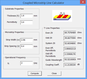
H 16mm and er 34. Even mode Losslen 00808908. Show activity on this post.
1 The first step is to select an appropriate low pass prototype. C frac 1 2 pi cdot Z cdot f_L L frac Z 2 pi cdot f_H Passive bandpass filter 2nd order. Tapped input hairpin Filter III.
Popular and relatively practical to design. When it comes to GHz frequency range the coupled-line microstrip bandpass filter is. Odd mode Loss 00740294.
Coupled-line microstrip bandpass filters are easy to design for narrow bands but for relatively large band it becomes complex as more parameters are need to be considered. Enter the substrate parameters. Passband insertion and return loss is.
This video shows calculation method on design coupled line bandpass filter. The MWO Transmission Line Calculator Next a schematic diagram of the filter is constructed as in fig 3. Coupled input hairpin Filter Fig2.
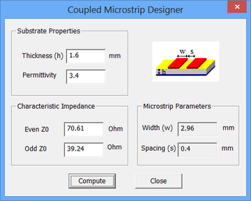
This video explain about how to calculate the value of admittance intervals and o. Enter the Z0e and Z0o values for the two types of coupled line segments from the previous section and calculate width and spacing of the coupled microstrip lines for each case. This CalcTown calculator calculates the resistances capacitances and bandwidth given the center frequency and quality factor of a narrow band-pass filter.
The design equations for parallel coupled bandpass filter given in terms of its admittance 1 5. INTRODUCTION Parallel coupled transmission-line filter in microstrip and stripline technology are very common for implementation of bandpass and band-stop filters with required bandwidth up to a 20 of central frequency. This active bandpass filter is composed first of a high-pass filter which is made up of resistor R1 and capacitor C1.
Please verify by simulation that attenuation above passband is sufficient. Open the Coupled Microstrips Designer dialog from the Tools Menu of Device Manager. A tapped structure is chosen for the external couplings.
This paper presents the design and test of a planar coupled line filter constructed from relatively high quality dielectric material. Note that X or em-based models are used wherever possible for better accuracy in the filter design. Microwave filter design.
V g L 11 L 21 C 21 C 31 L 31 11 C 1 1. The advantage of using this multiple feedback active band-pass filter is that one doesnt an inductor bulky and expensive at low frequencies to create the band-pass shape. Coupled Line Bandpass Filter.
These graphs are for symmetrical strip line in the form shown in Fig. Uses 22 pF SQCB low ESR capacitors from ACX RF TOKO LL2012-FHL Chip Inductors muRata 3-10 pF Trimmer and a wire capacitor for coupling. This calculator is an active inverting bandpass filter calculator.
Design Data for a 2-Resonator Bandpass Filter. The model is solved for the S-parameters and a very narrow bandwidth is observed. 0 n 2 1 Z0JN1 2 1 Where g0 g1gn is the element of a ladder-type lowpass prototype with a normalized cutoff frequency and FBW is Shape ratio for the.
The formulas for calculating coil and capacitor are. When one is on the other off. LC Filter Design Tool Calculate LC filters circuit values with low-pass high-pass band-pass or band-stop response.
The two components filter out very high and very low frequencies. The output is the inverted input signal which means the input signal and output signal are 180 degrees out of phase. Nowadays microstrip bandpass filters designed from coupled line have been widely used in many wireless communication applications.
This paper presents the design and test of a planar coupled line filter constructed from relatively high quality dielectric material. Parallel Coupled-Line Combline Filter. The bandpass coupled line filter presented here is specified to have a midband at 169GHz and bandwidth of 0169GHz.
The bandpass coupled line filter presented here is specified to have a midband at 169GHz and bandwidth of 0169GHz. This paper presents an implemented calculator tool for the design of Edge Parallel Coupled Microstrip Band Pass Filters PCMBPF that makes use of the MATLAB software. Generally coupled line inputs are fine for narrow band.
12 Z0e Z0o JZ02 Z0J1 2 1 Z J for n 2 3 N. My results from the schematic look great. Transmitted and received signals have to be filtered at a certain center frequency with a specific bandwidth in this paper a coupled-line bandpass Filter at the center frequency 6 GHz with the.
This project the design of bandpass filter at the frequency of 24 GHz with parallel-coupled microstrip will be implemented. Passband insertion and return loss is. When I move to the layout and EM simulation my results look nothing close to a bandpass filter.
Other formulas are available to design end-coupled filters up to approximately the same bandwidths. This is the simplest way to build a bandpass filter. It is possible to realize a narrowband bandpass filter using cascaded microstrip coupled lines.
Part B 8 Filter design is based on circuit transformations. I am trying to design a microstrip bandpass filter in ADS with a center frequency of 24GHz and a fractional BW of 10. This design has the.
The equations by Bradley and Cohn in the reference cited are used here to construct graphs for determining band-pass filter dimensions as a function of normalized bandwidth. Microstrip technology Also low fabrication cost and very good performance 2.

Coupled Line Bandpass Filters Youtube

Schematic Circuit Of Parallel Coupled Microstrip Bpf With Agilent Ads Download Scientific Diagram

1 Parallel Coupled Band Pass Filter At 3 2 Ghz Results Using Tool Download Scientific Diagram

1 Parallel Coupled Band Pass Filter At 3 2 Ghz Results Using Tool Download Scientific Diagram

Parallel Coupled Band Pass Filter Calculator First Interface Download Scientific Diagram
Rf Tutorial Lesson 7 Designing Distributed Bandpass Filters Using Coupled Transmission Line Segments Emagtech Wiki
Design Coupled Line Bandpass Filter Part 2 Simulation Youtube
Rf Tutorial Lesson 7 Designing Distributed Bandpass Filters Using Coupled Transmission Line Segments Emagtech Wiki
0 comments
Post a Comment